AD8313
AD8313 is Logarithmic Detector/Controller manufactured by Analog Devices.
FEATURES
- Wide bandwidth: 0.1 GHz to 2.5 GHz min
- High dynamic range: 70 d B to ±3.0 d B
- High accuracy: ±1.0 d B over 65 d B range (@ 1.9 GHz)
- Fast response: 40 ns full-scale typical
- Controller mode with error output
- Scaling stable over supply and temperature
- Wide supply range: 2.7 V to 5.5 V
- Low power: 40 m W at 3 V
- Power-down feature
: 60 m W at 3 V
- plete and easy to use
APPLICATIONS
- RF transmitter power amplifier setpoint control and level monitoring
- Logarithmic amplifier for RSSI measurement cellular base stations, radio link, radar
GENERAL DESCRIPTION
The AD8313 is a plete multistage demodulating logarithmic amplifier that can accurately convert an RF signal at its input to an equivalent decibel-scaled value at its dc output. The AD8313 maintains a high degree of log conformance for signal frequencies from 0.1 GHz to 2.5 GHz. Application is straightforward, requiring only a single supply of 2.7 V to 5.5 V and the addition of a suitable input and supply decoupling. Operating on a 3 V supply, its 13.7 m A consumption (for TA = 25°C) is only 41 m W. A power-down feature is provided; the input is taken high to initiate a low current (20 µA) sleep mode, with a threshold at half the supply voltage.
The AD8313 is fabricated on Analog Devices, Inc., advanced 25 GHz silicon bipolar IC process and is available in an 8-lead MSOP package. The operating temperature range is
- 40°C to +85°C.
Table 1. Next Generation Upgrades for AD8313
Part Number ments
ADL5513 AD8318 AD8317
AD8319
Improved range and temperature stability, operation up to 4 GHz
Improved temperature stability, operation up to 8 GHz
Lower input range, improved temperature stability, operation up to 10 GHz
Lower input range, improved temperature stability, operation up to 10 GHz
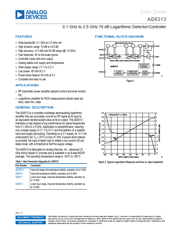
FUNCTIONAL BLOCK DIAGRAM
Figure 1.
Figure 2. Typical Logarithmic Response and Error vs. Input Amplitude
Rev. F DOCUMENT FEEDBACK TECHNICAL SUPPORT
Information furnished by Analog Devices is believed to be...